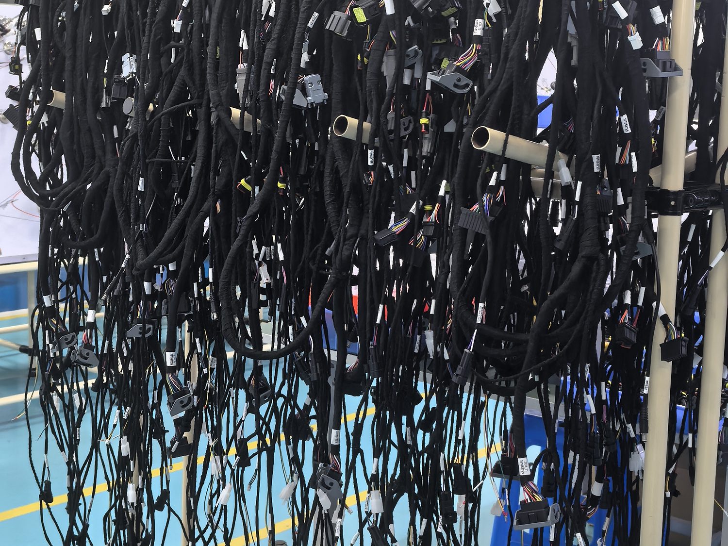
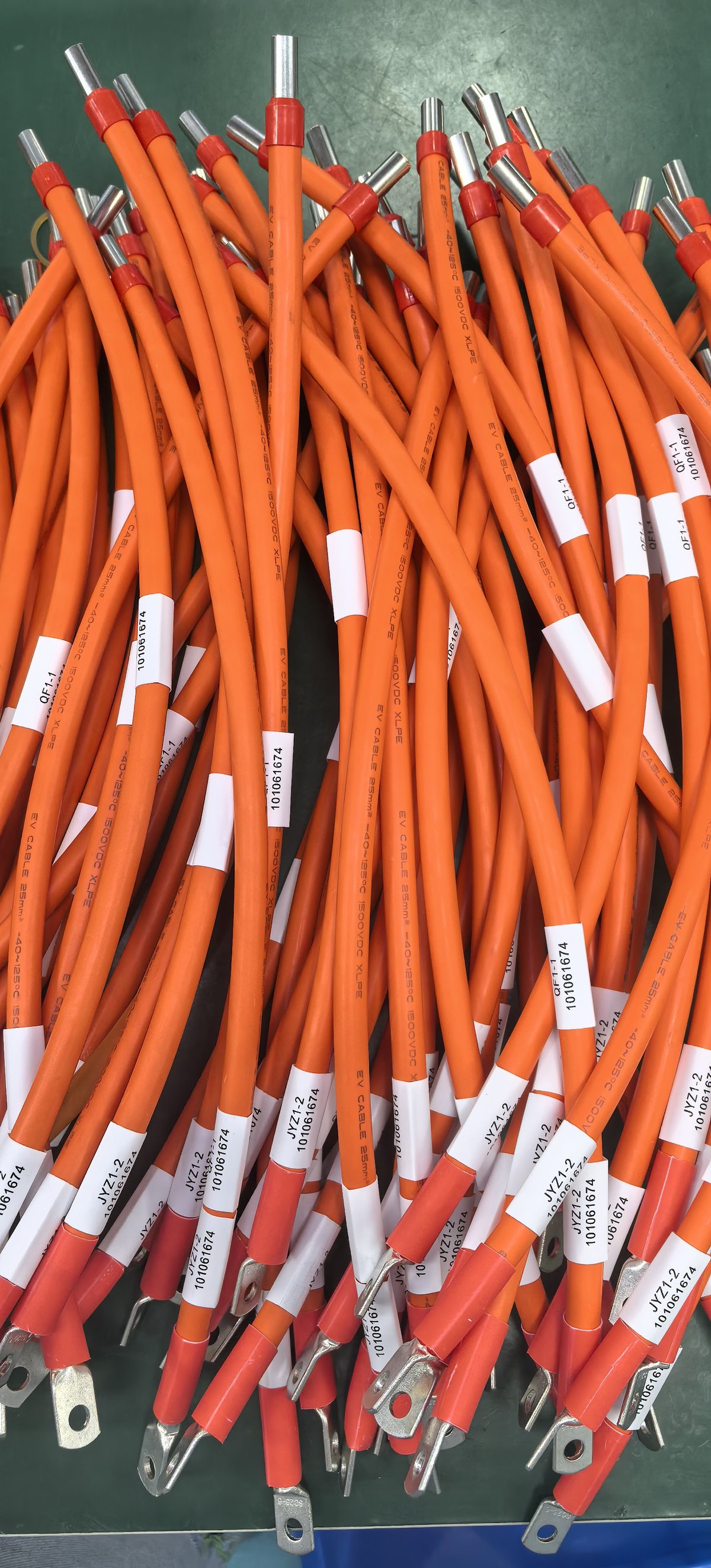
Four decisions set a harness before a single terminal is crimped: the wire gauge, the insulation, the connector, and the routing. Each one has an answer that can be calculated or checked, and each one gets made by default in most programmes — by copying the previous part, or by whatever the supplier stocks.
This is the checklist we work through on a DFM review, in the order that the decisions constrain each other.
1. Wire gauge: three limits, and the tightest one wins
Gauge is not chosen from a table of "typical values". Three separate limits apply, and the correct gauge is the largest of the three:
- Current-carrying capacity. How much current the conductor can carry before its insulation reaches its rated temperature. This depends on the insulation rating, the ambient temperature and how many conductors in the bundle are carrying load at once.
- Voltage drop. How much voltage is lost along the run. On a 12 V or 24 V system this is frequently the binding limit, because the load is allowed a tolerance and the wire eats into it.
- Mechanical requirement. A cable that is handled, flexed or routed through a grommet has a minimum size below which it becomes damage-prone regardless of current.
As a rule of thumb — and it is only that, because it moves with all three factors above — a single conductor in free air at a 105 ℃ insulation rating carries roughly 5 to 7 A at 20 AWG, 8 to 10 A at 18 AWG, 12 to 15 A at 16 AWG, 18 to 20 A at 14 AWG and 25 A at 12 AWG. In a bundled harness those numbers fall, which is why the conductor datasheet and not this paragraph is the document to design against.
The voltage drop calculation that gets skipped
For a two-wire run, the drop is:
V_drop = (2 × L × I × ρ) ÷ A
where L is the one-way length in metres, I the current in amperes, ρ the resistivity of copper (about 0.0172 Ω·mm²/m at 20 ℃) and A the conductor cross-section in mm². The factor of two is the return path — the single most commonly forgotten term in the whole calculation.
Worked example: a 12 V circuit drawing 8 A, three metres one way, with 0.4 V of drop allowed.
Ampacity alone would have allowed 18 AWG on this circuit. The voltage drop requirement makes it 14 AWG — two sizes larger, and a materially different harness. This is worth checking at design stage, because a gauge revision after tooling is a new part.
2. Insulation: temperature first, then everything else
The insulation choice follows the hottest temperature the conductor will see, not the ambient the vehicle sits in. Three materials cover most programmes:
The two errors that recur: specifying silicone everywhere because one circuit is hot, and specifying a wall thickness that makes the bundle too stiff to route. A harness is usually a mix, and a drawing that names the material per circuit rather than globally is both cheaper and more buildable. See the full material comparison for the trade-offs in more detail.
3. Connectors: four things beyond the part number
A connector part number is not a specification. Four more items belong on the drawing, and each one changes either the cost or the failure mode:
- Terminal plating. Tin is the default; gold is for low-current signal circuits in humid or high-vibration environments, where a tin oxide film on a low-current contact is a real failure mode.
- Sealing. Whether the connector is sealed, and whether the seal is in the housing or a separate wire seal. A sealed housing with an unsealed cavity is a common and silent mismatch.
- Terminal retention. The secondary lock or retainer position, and whether it is verified at end of line rather than left to the operator.
- Keying and colour. Two identical connectors on the same harness that can be swapped is a designed-in failure. Keying, colour and cavity numbering are what prevent it; if they are not on the drawing, the operator will invent them.
4. Routing and protection
Routing is where a harness that checks out on the bench fails in the vehicle. The items most often missing from a drawing set:
- Minimum bend radius, stated as a multiple of the outside diameter, and the locations where the radius is tight.
- Fixed points, their positions, and the free length between them so the harness can move where it is meant to.
- Clearance to heat sources and moving parts, with the temperature at each point rather than a general note.
- Protection by zone — conduit, braid, tape or none — and the wrap direction, which decides whether water runs along the harness or off it.
- Measured-from datum for every branch. Branch lengths referenced to a connector face accumulate error the length of the harness; branches referenced to a fixed datum do not.
The checklist in one page
Where the checklist lands by family
- An automotive harness — engine, chassis or cabin — is where voltage drop and heat clearance do the most work, and where the drawing usually exists in enough detail to review properly.
- On an EV high-voltage assembly, the gauge question is replaced by a construction question: the conductor size follows the continuous current, but the shielding, the bend radius and the termination method are what the supplier is being asked to decide.
- On a construction machinery harness, protection and fixed points carry more weight than on a road vehicle — the harness lives in a wash-down, high-vibration, wide-temperature environment and is often serviced in the field.
- On an industrial automation harness, the design driver changes to flex life. A drag-chain or robot cable is specified by cycle count and minimum bend radius, and the gauge follows from the load rather than from the routing.
Frequently asked questions
How do I choose the wire gauge for a 12 V circuit?
Work out the three limits and take the largest. Calculate the voltage drop with V_drop = (2 × L × I × 0.0172) ÷ A, remembering the factor of two for the return path, then check the ampacity from the conductor datasheet at your insulation rating and ambient temperature, then check that the cable is not too thin to survive how it will be handled. Voltage drop is the binding limit on most low-voltage circuits longer than about two metres — a circuit that looks fine on an ampacity table can lose 15% of its supply voltage over a five-metre run.
Can I use silicone insulation for the whole harness instead of specifying it per circuit?
You can, and it will work, but you will pay several times the necessary cost and lose abrasion resistance across the whole bundle — silicone is more temperature-tolerant but less tough than XLPE, so a silicone harness in a chafing location needs more protection, not less. The usual compromise is XLPE as the default with silicone only on the circuits that actually reach high temperature. That requires the drawing to state the temperature at each zone, which is worth doing anyway because it is the same information that decides protection and clearance.
Why do branch lengths need a datum rather than being measured connector to connector?
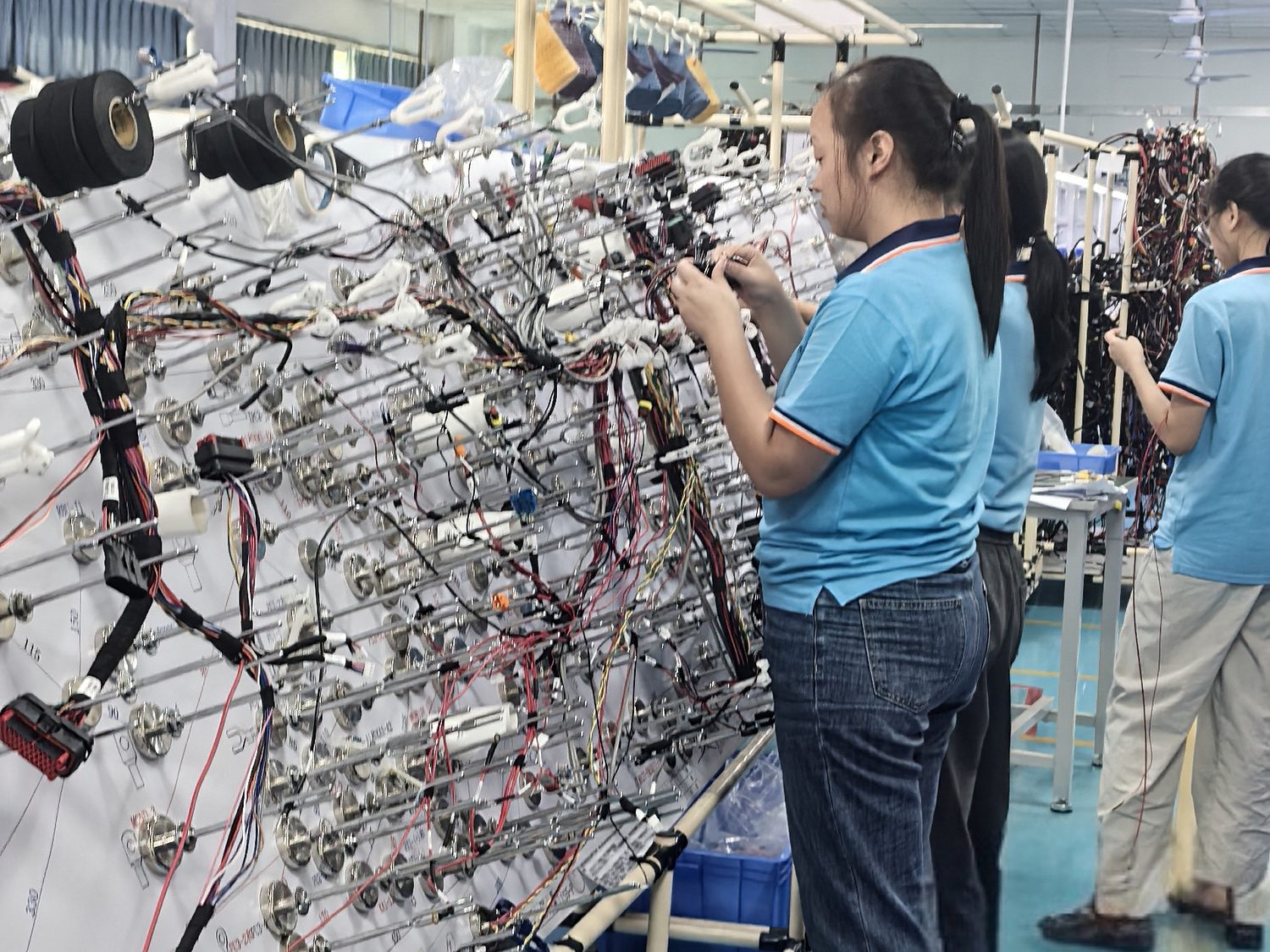
Because errors accumulate along the harness. If each branch is dimensioned from the previous connector face, every tolerance in between adds to the last one, and the final branch carries the sum. Dimensioning every branch from a single fixed datum keeps each tolerance independent, so the last break-out is as accurate as the first. It also makes the drawing easier to check and the harness noticeably easier to build on a forming board, which is where a great deal of the cost of a complex harness actually sits.

 Guides & Insights · Sep 24, 2026